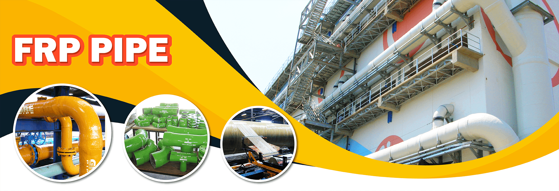
GRE PIPE
GRE pipe is manufactured by filament winding technique, providing great strength property to the pipe. GRE pipe is designed in compliance to ASTM D 2996, DIN 16965 and TIS standards. GRE piping systems utilize epoxy or vinyl ester resins as corrosion barriers and fiberglass for their structural strength.
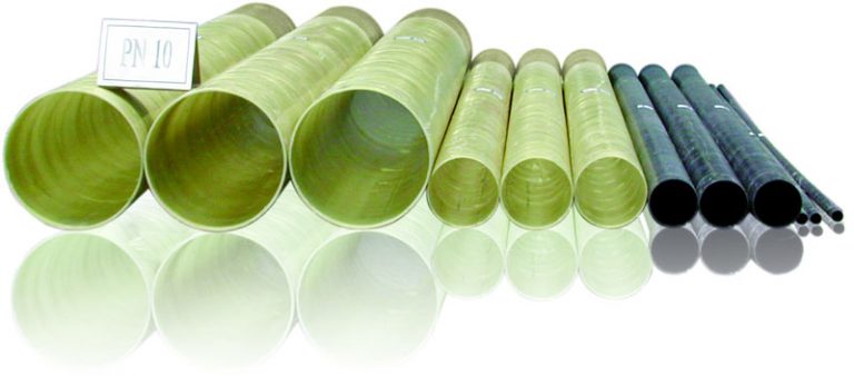
What is GRE or GRP or GRVE pipe use for?
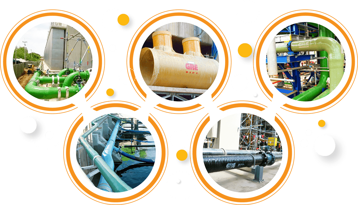
Glass fiber reinforced plastic (GRP) or Glass fiber reinforced epoxy (GRE) are a composite material made of a polymer matrix reinforced with fibers.
GRE pipe is designed for corrosion resistance, weather resistance, visual inspection friendliness and durability.
Fiberglass pipe has great unsupported strength capability, corrosion resistant interior and exterior, is light weight and easy to fabricate / install and has a very smooth interior for higher flow rates, reducing energy consumption. The thermal conductivity of GRE pipe is low compared to steel and hence heat loss and insulation cost is minimized.
GRE pipe also has a smooth internal surface enables high pipe flow capacity and reduces friction as well. It can be not only easily installed but also free maintenance.
DESIGNED FOR THESE APPLICATIONS
STANDARD : ASTM D 2996, DIN 16965, TIS 1483, TIS 1484, TIS 1485
- Brine transmission and desalination
- Chemical processing and steam condensate return
- Fire water/fire protection pipe
- Oil & gas transmission
- Offshore cooling water and drainage
- Acid transportation
- Sewage and sanitary service
- Seawater transport line
- Water and waste water pipe line

Designed standard
ASTM D 3299
ASTM D 4097
ASME RTP-1
TIS 435
ANSI/AWWA D 120

Designed for these applications
- Brine transmission and desalination
- Chemical processing and steam condensate return
- Fire water/fire protection pipe
- Oil & gas transmission
- Offshore cooling water and drainage
- Acid transportation
- Sewage and sanitary service
- Seawater transport line
- Water and waste water pipe line
PRODUCTION
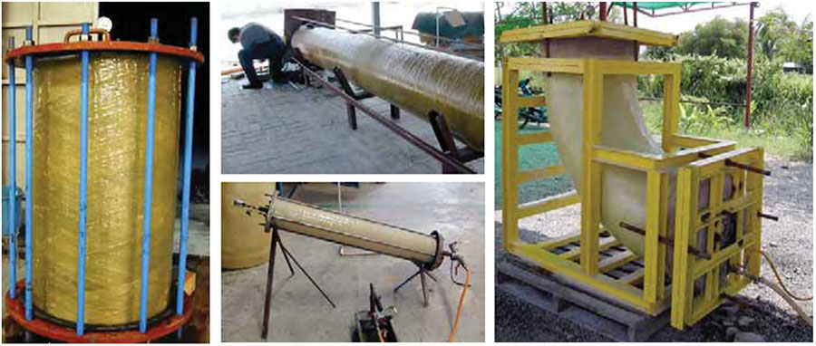
GRE pipe technology is based on the Filament Winding process using high strength fiberglass (E-glass) and amine cured epoxy resin as basic material. Numerically controlled machines manufacture the product on a mandrel according to the cross section filament winding process. The continuous glass fibers are helically wound at predetermined angles and bonded with the epoxy resin.
The mechanical resistant layer is composed of successive layers of pre-stressed glass roving impregnated with epoxy resin and orientated with a precise, predetermined angle selected in order to achieve the properties required.
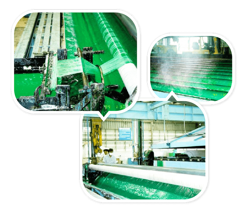
GRE pipe is generally manufactured with an integral joint, which means that the socket (for bonding, lock, or thread) is produced simultaneously with the pipe body by winding on a specially designed metallic mold fixed at one end of the mandrel. The pipes are wound on precisely machined steel mandrels, the mandrel is extracted only when the pipe is cured.
FEATURE & BENEFIT
GRE pipe is resistant for corrosion both inside and outside, in wide range of fluid handling applications. The pipe can be laid in any environmental conditions without any extra protection
GRE pipe has a smooth internal surface that reduces friction and enables a high pipe flow capacity. Low thermal conductivity of GRE pipes in comparison to steel (only one percent of steel values), minimizes the cost of insulation and the heat loss. Another major benefit of GRE pipes is that once installed they are virtually maintenance-free.
GRE pipe has excellent strength to weight properties. When the ratio of strength per unit of weight is considered. GRE pipe surpass iron, carbon and stainless steel.
GRE pipe from 25mm (1”) up to 1400 mm (54”) has temperature capabilities up to 110 °C (epoxy resin)
GRE pipe is easily jointed together by using many types of joining system such as integral bell-spigot end, butt joint kit lamination, grooved coupling and weld neck flange joint, FF type (ASME B16.5, Class 150)
GRE pipe is easy to maintain because it does not rust and requires minimal protection from the environment.
GRE pipe has a complete line of standard fitting. Custom fabricated fitting is available upon request.
- Long life (50 years) + Zero maintenance = low life cycle cost.
- UV resistant can be safely installed for above ground installation.
- Lighter support needed for above ground systems.
- Conductive pipe and fittings are available.
- Fast, low cost assembly due to light weight and simple jointing techniques.
TESTING METHOD
(ASTM D 2996)
According to the ASTM D3567 standard, a test specimen is outside diameter or inside diameter, thickness and length. Outside diameter: measure the outside diameter at both end pipe of each it and report the result of experiment. Thickness: measure the thickness of pipe at various point follow the direction of circumference at least 4 values and report the result of experiment both minimum and average values. Length: measure the length of pipe at 2 points that opposite together and report the result of experiment.
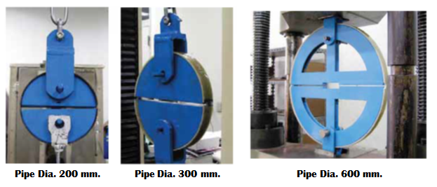
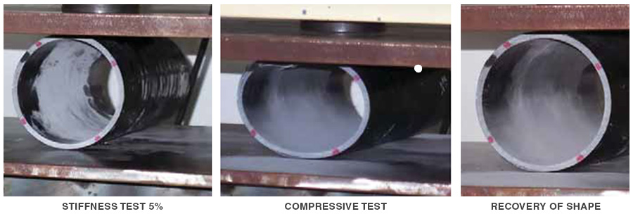 Test method is carried out in reference to ASTM D 2412 standard. A specimen with its longitudinal axis parallel to the plate is located in the testing machine. After applying the force to the desired deflection, the load is recorded. The force is continuingly applied until the specimen breaks and the ultimate compressive strength value is recorded. Due to the memory capability, pipe display excellent capability to retain its shape after the removal of the load.
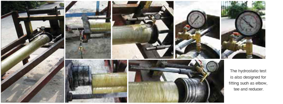
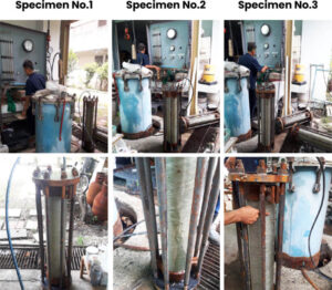
( Picture1 : show the hydrostatic pressure testing of Pipe DN600 (PN25) and maximum test pressure at 37.5 bar. )
The pipe and fitting shall be test 1.5 time of design pressure before delivery.
( Picture2 : show the hydrostatic pressure testing of 90 Elbow DN600 (PN25) and maximum test pressure at 37.5 bar. )
( Pictures4 : Show the hydrostatic pressure testing of Heavy Duty WN-Flange DN600 (PN25) and maximum test pressure at 37.5 bar. )
According to ASTM D1599 and ASTM D2992 standards, a pipe specimen is attached to the end closures and filled with water. The pressure level is increased by using a pressuring device until the specific test pressure has been reached. The test pressure is ranging from 2 bars for non-pressure pipe to 50 bars for reverse osmosis membrane housing pipe.
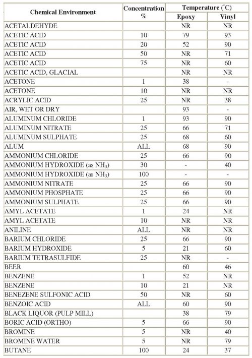
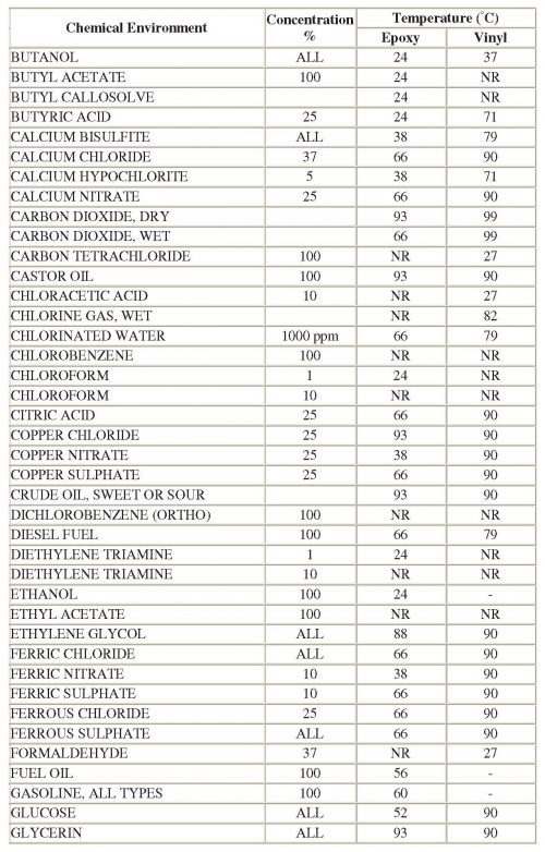
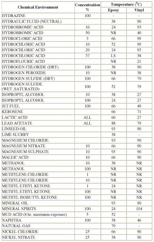
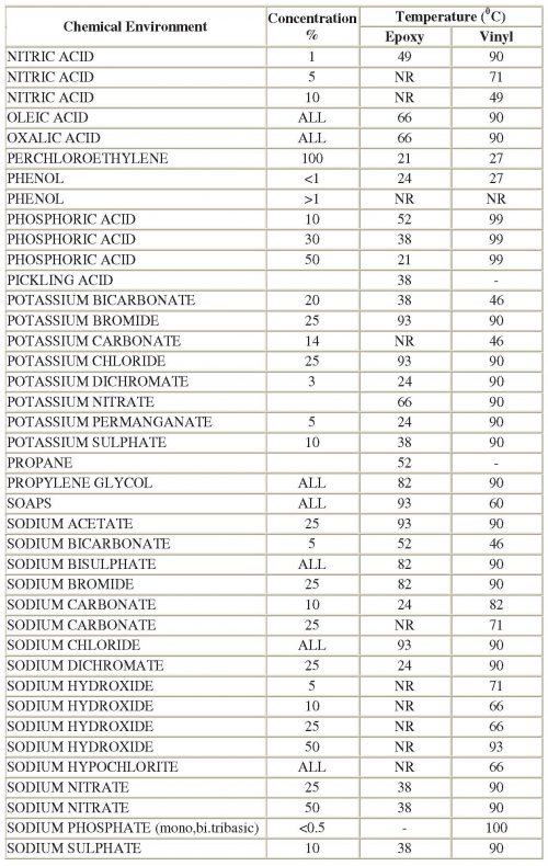
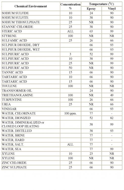
*** This chemical table is only a guideline information which may be changed according to the resin used. ***
